$113.00
* +4% Order Processing Fee applies. No extra payment service fees.
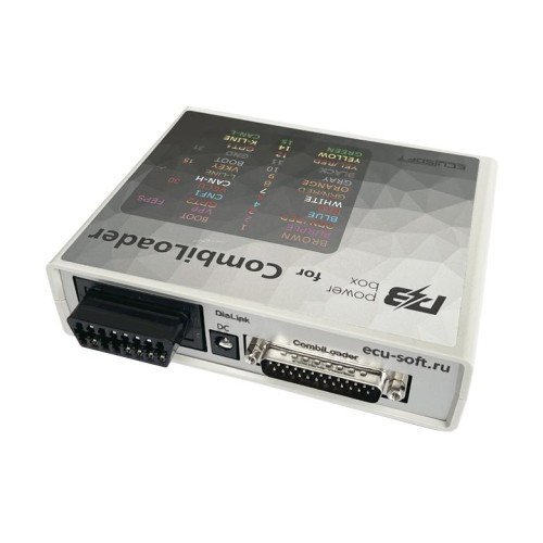
Adapter for connecting the control unit "on the table", switching power supply voltages and GPT1, GPT2, as well as generating BOOT and CNF1 signals. Fully compatible with the CombiLoader bootloader and can also be used manually with any bootloader that has "manual control logic".
Control elements:
The device is equipped with three switches for operation in different modes.
- GPT switch.
When this mode is activated, the signal lines 7 and 15 of the DiaLink connector are connected to the DB-15 connector (GPT1 and GPT2), and the power supply is simultaneously disconnected from the DiaLink connector. It is used for reading the password in GPT mode. In the off state, the signal lines 7 and 15 are connected to the DB-15 connector (K-line and L-line), and the GPT1 and GPT2 lines are de-energised.
- POWER switch, power control.
The device has three power supply modes for the ECU:
OFF - power off, allows to disconnect all power and control signals from the DB-15 connector.
MANUAL - power on, provides power to the VECU and VKEY terminals, as well as control outputs depending on the selected BOOT switch mode.
AUTO - automatic control, in this mode, power control is performed by the CombiLoader.
- BOOT switch, simultaneous control of BOOT and CNF1 signals (3.3 volts):
OFF - power off, allows to disconnect all control signals from the DB-15 connector.
MANUAL - power on, pulls BOOT to the signal ground, and CNF1 to +3.3 volts.
AUTO - automatic control, in this mode, simultaneous control of signals is performed by the bootloader.
The device has built-in current-limiting resistors on the signal lines:
- RESET - 510 Ohm
- BOOT - 510 Ohm
- CNF1 - 510 Ohm
- CAN - 120 Ohm
Connectors:
The device is equipped with connectors for peripheral connection.
The DC connector is intended for power supply.
The J2534 connector is designed for connecting the corresponding interface with the OBD-II connector.
The connector has the following pinout:
- 4 GND
- 5 GND
- 6 CAN-H
- 7 K-LINE
- 13 VPP
- 14 CAN-L
- 15 L-LINE
- 16 POWER
The DB-15 connector is designed for connecting the ECU.
Attention! DB15 cable is not included and must be purchased separately.
The connector has the following pinout:
- 1 RESET BROWN
- 2 VPP PURPLE
- 3 GPT2 ORANGE
- 4 CNF1 BLUE
- 5 VECU RED
- 7 CAN-H WHITE
- 9 VKEY ORANGE
- 10 BOOT GRAY
- 11 GND BLACK
- 12 GPT1 YELLOW/ RED
- 14 K-LINE YELLOW
- 15 CAN-L GREEN
Indicators:
- The GPT LED indicates the activation of the corresponding mode.
- The VECU and VKEY LEDs indicate the presence of VECU and VKEY voltages.
- The 12V LED indicates the presence of power supply voltage.
- The BOOT LED indicates the presence of pull-ups on CNF1 and BOOT.
Important:
This function is available only on certain BMW engines and is NOT applicable to other vehicle brands.
The information below applies only to stock engines with factory ECU software and a standard exhaust system.
What This Parameter Actually Represents
This is NOT a direct measurement of fuel octane and is NOT a direct octane reading calculated by the ECU.
The value is an adaptation factor ranging from 0 to 1, where:
- 0 = no correction
- 1 = maximum correction
According to BMW’s internal definition:
Faktor adaptierte Kraftstoffqualität (0 = ROZ98 / 1.0 = ROZ91)
- 0 corresponds to 98 ROZ
- 1.0 corresponds to 91 ROZ
ROZ is the German equivalent of RON (Research Octane Number).
The device converts this multiplier into a more intuitive octane value for user convenience.
⚠️ The device does not measure anything itself.
It only displays the data provided by the engine control unit (ECU).
How the ECU Evaluates Fuel Quality
Each ECU has different calibration sensitivity:
- Sensitivity to the adaptation factor
- Sensitivity of the knock control system
Fuel quality is evaluated subjectively by the ECU, primarily based on:
- Knock ignition timing corrections
- Overall engine noise levels
BMW G-Series & LCI F-Series (B-Engines)
B38 / N63 / S63 / N74
These engines are highly sensitive to octane adaptation.
- During warm-up and cruising, the displayed octane may frequently drop to 95 or lower.
- This does NOT automatically indicate poor fuel quality.
- Under load, the value should increase.
⚠️ If the value continues to decrease under load, this may indicate a problem.
B46 / B48 / B58
These engines have low sensitivity.
- During cruising, octane will typically display maximum values even with mediocre fuel.
- Under load, the value will decrease if fuel quality is truly poor.
S58
Octane correction is virtually inactive.
- It will typically always show 98.
- If it drops below 98, fuel quality is genuinely very poor.
BMW F-Series (Pre-LCI) with N/S Engines
Most pre-LCI F-series ECUs do not calculate octane adaptation.
Do not expect this parameter to function.
S55
- Octane parameter not used by the system
- Display not supported
- However, display of the last 5 refueling quality events is supported
S63
- Octane parameter not used
- Display not supported
- Refueling quality display not supported
BMW E-Series
Octane parameter not available. Display not supported.
Important Notes About Tuned Vehicles
With modified hardware or custom tuning, behavior may vary significantly. Always consult your tuner regarding expected operation.
Key principles:
- If octane drops under load, it means fuel quality is worse than expected under those conditions.
- This does NOT automatically mean the fuel itself is bad.
Examples:
- If a tuner increases ignition timing and boost pressure, even good fuel may cause knock corrections, and the ECU may interpret it as poor fuel.
- Thin-walled or poorly mounted exhaust systems may create parasitic noise, which the ECU may interpret as engine knock, causing negative correction.
- Conversely, if knock sensitivity is reduced or octane correction is disabled in tuning, readings may appear ideal while actual engine safety is compromised.


