
BITS002 Bench Adapter for BitBox – Automatic Power & Boot Control (J2534 / Scanmatik Compatible)
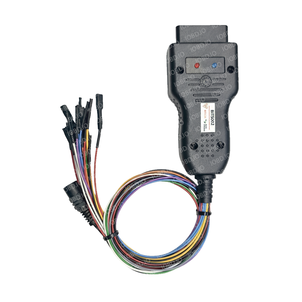
The BITS002 Bench Adapter is a specialized breakout interface designed for on-the-bench connection and flashing of modern automotive electronic control units (ECUs). Engineered specifically to work in tandem with the BitBox flasher software and J2534 Pass-Thru devices, it provides automated power switching and boot-pin line management directly through your hardware interface.
Equipped with a standard OBD-II female connector, the BITS002 seamlessly couples with high-performance J2534 interfaces such as Scanmatik SM2, SM2 PRO, and SM3, eliminating manual power toggling and external bench box complications.
It is purpose-built to operate with the updated BitBox module: Bosch MG1/MD1 Gen2 BSL/BENCH, unlocking reliable reading, writing, and bench servicing for post-06.2020 locked Bosch MG1 and MD1 control units.
Key Features & Benefits
- Automated Power & Boot Switching: Full automatic control of ECU power supply (+12V, GND) and Boot lines managed directly by the BitBox software protocol via J2534 lines.
- Direct J2534 Integration: Features a robust OBD-II female port for instant plug-and-play connection to J2534 interfaces (Scanmatik SM2 / SM2 PRO / SM3).
- Locked ECU Support (06.2020+): Specifically engineered to meet the hardware timing and signaling demands of locked Bosch MG1/MD1 Gen2 ECUs in BSL/Bench modes.
- Full Signal Coverage: Includes dedicated leads for CAN, K-Line, Vpp, multiple Boot logic lines (Boot L0, Boot L1, Boot H0), and dual GPT synchronization lines (GPT1, GPT2).
- Durable Breakout Leads: High-flexibility color-coded wiring designed according to official BitBox documentation standards for error-free pin identification.
Pinout & Wire Color Coding
The pin configuration strictly corresponds to the official BitBox wiring diagrams and software specifications:
| Wire Color | Signal / Pin Assignment | Function Description |
| Red | +12V POWER | Main ECU Power Supply |
| Black | GND | Ground |
| Yellow | CAN-High | High-Speed CAN Bus |
| Blue | CAN-Low | Low-Speed / CAN Bus Return |
| Green | K-Line | Diagnostic Communication Line |
| Gray | Boot L0 | Boot Logic Low 0 |
| White | Boot L1 | Boot Logic Low 1 |
| Orange | Boot H0 | Boot Logic High 0 |
| Purple | Vpp | Programming Voltage Output |
| White / Red | GPT1 | General Purpose Timer Signal 1 |
| White / Black | GPT2 | General Purpose Timer Signal 2 |