Original Toolbox from SMS-Soft for Combiloader (PowerBox)
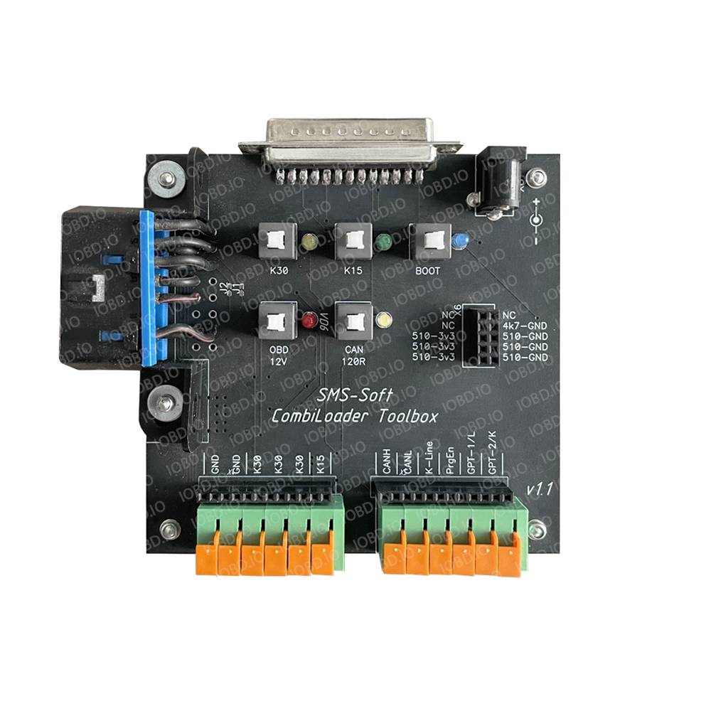
Device Design the Toolbox is an open, caseless board protected from accidental short circuits and mechanical impact by a plastic screen. All components are securely fixed, ensuring stable device operation.
Connections, Switches, and Contacts
Main Connectors:
- Top DB25 Connector – used for connecting the V3 bootloader adapter.
- 12V Power Connector – center contact is "plus," used to supply DC voltage. A power supply with adjustable voltage of 12–15V, a working load of 3A, and current consumption control is recommended. If overload protection is present, it should be disabled or set to the maximum threshold.
- Left OBD-II Connector – used for connecting the J2534 adapter.
The Toolbox is compatible with Dialink and SM2/SM2Pro adapters.
Functional Switches
- K30 – directly supplies constant power to the controller (K30), bypassing the bootloader adapter. A yellow LED indicates activation.
- K15 – supplies switched power to the controller (K15 "Ignition"), bypassing the bootloader adapter. A green LED indicates activation.
- OBD 12V – supplies 12V power to the J2534 adapter. A red LED indicates active status. The J2534 power should be turned off when working with BSM if the GPT level is 5V.
- CAN 120R – connects a 120-ohm terminator resistor between CAN-L and CAN-H. A white LED indicates activation.
- BOOT – manual control of Boot pins (black connector). A blue LED indicates manual mode activation.
Boot Pins and Bootloader Mode
The device has a boot block containing:
- Three signals pulled up to 3.3V via a 510-ohm resistor.
- Three signals pulled down to GND via a 510-ohm resistor.
- One signal pulled down to GND via a 4.7 kΩ resistor.
By default, boot pins are inactive and only connect automatically via the bootloader command or manually by pressing the BOOT button.
When powering on the device, all switches except OBD 12V must be off to enable automatic power line switching and bootloader control.
Forced activation of power lines and boot mode is generally not required, as switching is handled by the bootloader. The necessity for manual activation is specified in programming manuals for certain ECUs.
Controller Connection
The bottom row of connectors is designed for standard bus connections: GND, K30, K15, CAN, K-Line, GPT. Connection is made using the supplied cables and adapters. Wires are securely fixed in the connector, and to disconnect, press the corresponding latch.
A black pin header next to the main block duplicates the primary connector.
Usage with Dialink (pre-2019 versions)
Before using Toolbox, early Dialink users should check the adapter. When pressing the "ECU Identification" button, hold Ctrl:
- If the message "Dialink (Normal)" appears, no additional action is required.
- If the message "Dialink (JmpReq)" appears, solder both J1 and J2 jumpers located near the OBD-II connector.
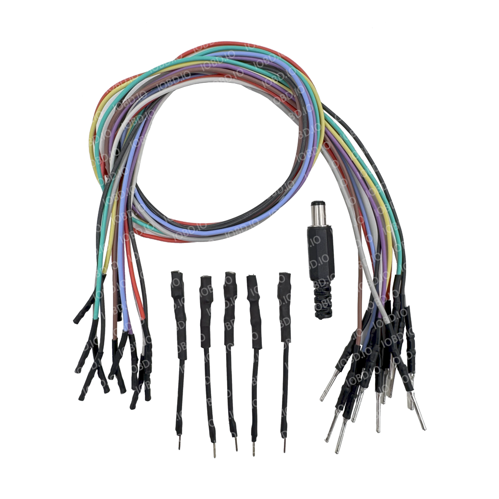
SMS-Soft Combiloader Toolbox Package Contents
- SMS-Soft Combiloader Toolbox – 1 pc.
- Wires with connectors (colored) – 11 pcs.
- Adapters for large ECU contacts – 4 pcs.