$119.47
* +4% Order Processing Fee applies. No extra payment service fees.
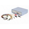
The CombiBox switching device is designed to connect the control unit to the PCMflash software loader and J2534 adapter on the table, as well as to switch power voltages and generate BOOT and CNF1 signals.
The Combibox allows for the generation of GPT1 and GPT2 signals when using the J2534 diagnostic autoscaner Scanmatic 2 Pro, which allows for working with 53 and 71 PCMflash modules, as well as with new modules that require these signals.
To work with the device, it needs to be connected to a stabilised 12V voltage (the mating part of the connector is included in the package). When soldering the power wire, it is necessary to observe the correct polarity of the connection, as failure to do so can damage the device and the vehicle's control unit. When working with the ECU and Combibox, it is recommended to use adjustable power sources with a threshold voltage of up to 30 volts and a maximum current of at least 3 amps.
Connectors and connection schemes for the Combibox:
1. J2534 - for connecting the Scanmatic 2 Pro autoscaner
- 1 - GPT2
- 2 - GPT1
- 4 - GND
- 5 - GND
- 6 - CAN-H
- 7 - K-LINE
- 12 - SELECT BOOT
- 14 - CAN-L
- 15 - L-LINE
- 16 - +12V
2. DC IN 5A Max Jack - for connecting power to the device
3. DB-15 - for connecting to the ECU with a universal cable
- 2 - Purple, VPP
- 3 - Green-Brown, GPT2
- 4 - Blue, CNF1
- 5 - Red, VECU +12V
- 7 - White, CAN-H
- 9 — Orange, VKEY +12V
- 10 — Gray, BOOT
- 11 — Black, GND
- 12 — Yellow-Orange, GPT1
- 14 — Yellow, K-Line
- 15 — Green, CAN-L
Switches and their modes:
1. “POWER”, power control. The device has three power supply modes for the ECU:
- “OFF”, turned off, disconnects all power and control signals from the DB-15 connector.
- “ON”, turned on, supplies power to the VECU and VKEY terminals, as well as control outputs depending on the selected BOOT switch mode.
- “AUTO”, automatic control, in this mode the power supply is controlled by the PCMflash tool.
2. “Boot SW”, BOOT signal control:
- “OFF”, turned off, disconnects all control signals from the DB-15 connector.
- “ON”, turned on, pulls BOOT signal to the signal ground.
- “AUTO”, automatic control, in this mode the BOOT signal is controlled simultaneously by the PCMflash tool.
3. “CNF1”, CNF1 signal control (3.3 volts):
- “OFF”, turned off, disconnects all control signals from the DB-15 connector.
- “ON”, turned on, pulls CNF1 signal to +3.3 volts.
- “AUTO”, automatic control, in this mode the CNF1 signal is controlled simultaneously by the PCMflash tool.
The LED indicators on the front panel of the device:
- “Power IN” indicates the presence of power supply voltage;
- “Power OUT” indicates the presence of voltage on the ECU;
- “Boot ON” indicates the presence of BOOT signal pull-up;
- “CNF1 ON” indicates the presence of CNF1 signal pull-up.
Package Contents:
- CombiBox
- universal DB-15 cable
- power plug

