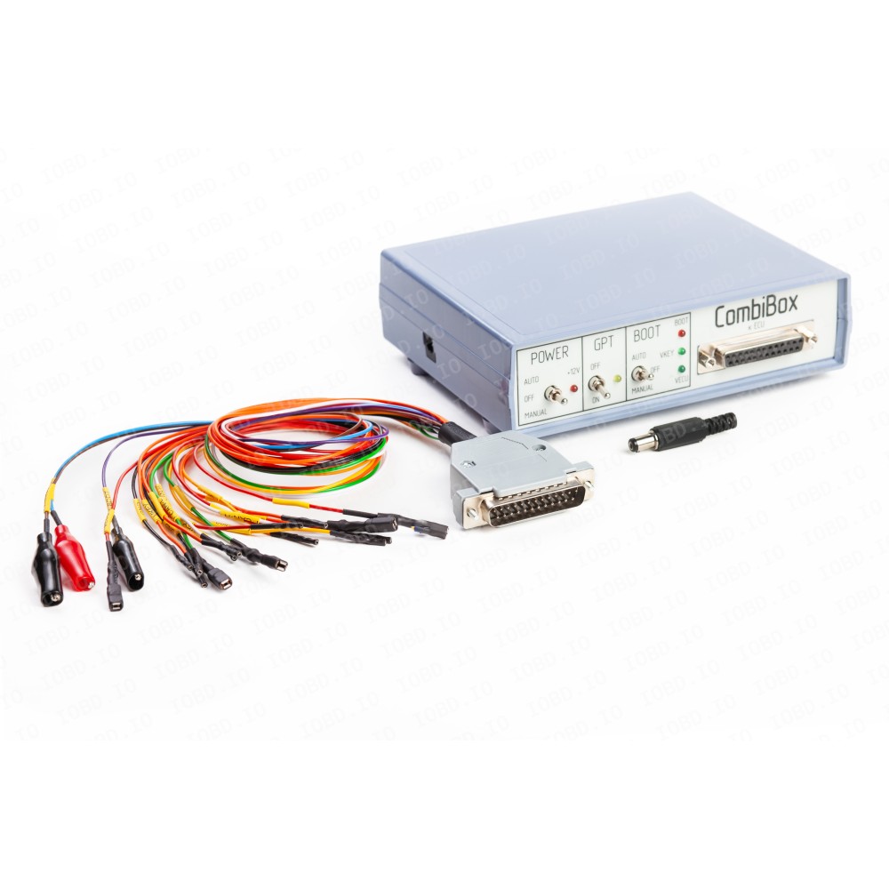

Commutation device CombiBox is designed for connecting the control unit to the software loader Combiloader and the adapter J2534 DIAlink on the table and for commutation of power voltages and signals GPT1, GPT2, and forming signals BOOT, CNF1.
To work with CombiBox, it is necessary to connect it to a stabilised voltage of 12V (the mating part of the connector is included in the kit). When soldering the power wire, it is necessary to observe the correct polarity of the connection, if the polarity is not observed, the device may be damaged, and also damage the control unit of the car. When working with ECU and CombiBox, it is recommended to use adjustable power sources with a threshold voltage up to 30 volts and a maximum current of at least 3 amperes.
Connectors and connection schemes to CombiBox:
1. DIALink - connector designed for connecting the corresponding adapter.
- 4 GND
- 5 GND
- 6 CAN-H
- 7 K-LINE
- 14 CAN-L
- 15 L-LINE
- 16 POWER
2. Combiloader - connector designed for connecting the corresponding adapter.
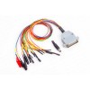
3. DB-15 - for connecting to the ECU with a universal cable.
The cable is equipped with additional pairs of contacts for the VECU and VKEY circuits, which in total allows up to eight power voltages to be applied (four small contacts and four large ones). For convenience, the GPT1 and GPT2 lines are separated together with additional CAN-H and CAN-L lines.
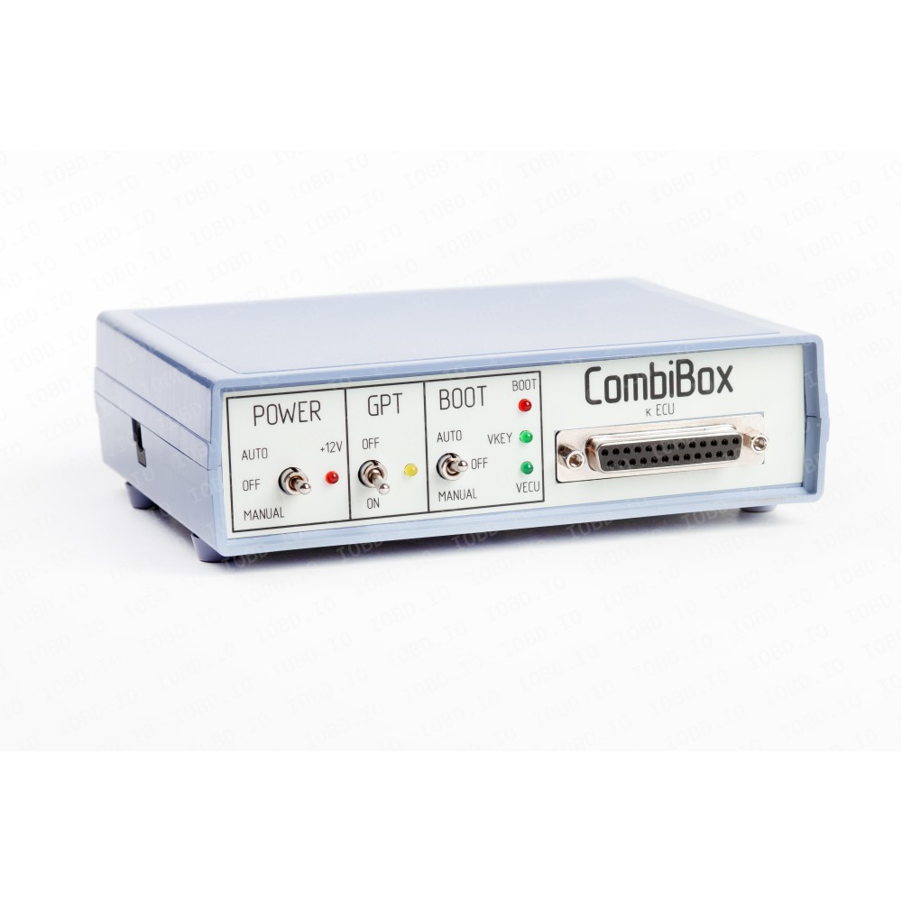
Switches and their modes:
1. GPT
When this mode is activated, the signal lines 7 and 15 of the DIALink connector are switched to the DB-25 connector (GPT1 and GPT2), and at the same time, power is removed from the DIALink connector. It is used for password reading in GPT mode. In the off state, the signal lines 7 and 15 are output to the DB-25 connector (K-line and L-line), and the GPT1 and GPT2 lines are de-energised.
2. POWER, power control
- OFF - turned off, allows to remove all power and control signals from the DB-25 connector.
- MANUAL - turned on, supplies power to the VECU and VKEY terminals, as well as to the control outputs depending on the selected BOOT switch operating tactic.
- AUTO - automatic control, in this mode, power control is performed by the CombiLoader.
3. BOOT, simultaneous control of BOOT and CNF1 signals (3.3 volts):
- OFF - turned off, allows to remove all control signals from the DB-25 connector.
- MANUAL - turned on, pulls BOOT to the signal minus, and CNF1 to +3.3 volts.
- AUTO - automatic control, in this mode, simultaneous control of signals is performed by the CombiLoader.
The device has built-in current-limiting resistors on the signal lines:
- RESET - 5.1 KOhms (for st10)
- BOOT - 510 Ohms
- CNF1 - 510 Ohms
- CAN - 120 Ohms
LED indicators on the front panel of the device:
- GPT indicates the activation of the corresponding mode.
- VECU, VKEY indicates the presence of VECU and VKEY voltage.
- 12V indicates the presence of power voltage.
- BOOT indicates the presence of pull-ups on CNF1 and BOOT.
Package includes:
- CombiBox
- universal DB-15 cable
- power plug